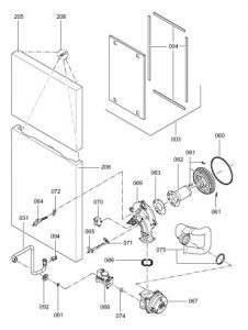
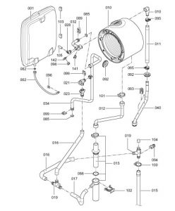
| 1 | | Diaphragm expansion vessel | | |
| 2 | | Connection line; diaphragm expansion vessel | | |
| 3 | | Cap panel with gasket | | |
| 4 | | Profiled seal | | |
| 5 | | Boiler flue connection | | |
| 6 | | Plug | | |
| 7 | | Ventilation air gasket | | |
| 8 | | Flue gas gasket | | |
| 10 | | Heat exchanger | | |
| 11 | | Moulded hose, return | | |
| 12 | | Condensate hose | | |
| 13 | | Siphon | | |
| 15 | | Hose (600 mm long) | | |
| 16 | | Condensate hose (400 mm long) | | |
| 17 | | Hose (270 mm long) | | |
| 19 | | Tee | | |
| 21 | | Safety valve | | |
| 23 | | Hose ferrule | | |
| 24 | | Right-angle shut-off valve, DHW cylinder heating | | |
| 25 | | Connection line, DHW heating | | |
| 26 | | Bezel | | |
| 27 | | Non-return valve | | |
| 28 | | Air vent valve G ?" | | |
| 29 | | Pressure gauge | | |
| 30 | | Right-angle shut-off valve, cylinder cold water | | |
| 31 | | Gas pipe | | |
| 32 | | Flow pipe | | |
| 33 | | Connection pipe, cold water, cylinder | | |
| 34 | | Heating water flow connection pipe | | |
| 35 | | Connection pipework, heating water return | | |
| 36 | | Connection pipework, cold water | | |
| 37 | | DHW connection pipe | | |
| 38 | | Heating water flow connection pipe | | |
| 39 | | Cold water connection | | |
| 40 | | Return connection pipe | | |
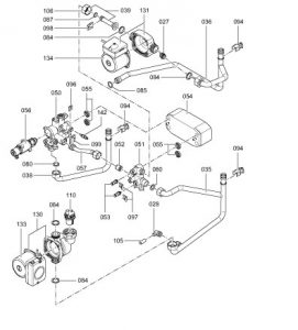
| 50 | | Flow unit | | |
| 51 | | Return unit | | |
| 52 | | Overflow valve | | |
| 53 | | Plug Ø 8/10 | | |
| 54 | | Plate-type heat exchanger | | |
| 55 | | Profiled gasket | | |
| 56 | | Valve insert | | |
| 57 | | Overflow pipe | | |
| 62 | | Burner gauze assembly | | |
| 63 | | Burner gauze assembly gasket | | |
| 66 | | Gasket burner flange | | |
| 66 | | Mixture damper | | |
| 67 | | Fan | | |
| 68 | | Gas train | | |
| 69 | | Burner door | | |
| 70 | | Ignition unit | | |
| 71 | | Ionisation electrode gasket | | |
| 72 | | Ignition electrode gasket | | |
| 74 | | Gas nozzle | | |
| 75 | | Venturi extension | | |
| 80 | | Gasket set A 16 x 24 x 2.0 | | |
| 81 | | Gasket set A 17 x 24 x 2.0 | | |
| 82 | | Gasket set A 10 x 15 x 1.5 | | |
| 84 | | Gasket 23 x 30 x 2.0 | | |
| 85 | | O-ring gasket set 17.86 x 2.62 | | |
| 87 | | O-ring 14.3 x 2.4 | | |
| 88 | | O-ring 35.4 x 3.6 | | |
| 89 | | Set of plug connector retainers | | |
| 90 | | Toggle fastener (set) | | |
| 92 | | Grommet | | |
| 93 | | Pipe clip Ø 18 | | |
| 94 | | Pipe clip Ø 18/1.5 | | |
| 95 | | Hose clip DN 25 | | |
| 96 | | Clip Ø 8 | | |
| 97 | | Clip Ø 10 | | |
| 98 | | Clip Ø 15 | | |
| 99 | | Clip Ø 18 | | |
| 100 | | Hose clip Ø 34.3-38.7 | | |
| 101 | | Worm-drive hose clip Ø 34.0 -37.4 | | |
| 102 | | Locking clip, condensate drain | | |
| 103 | | Drain plug (set) | | |
| 104 | | Cap | | |
| 105 | | Hose Ø 10 x 1.5 x 750 | | |
| 106 | | Union nut G 1" | | |
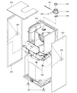
| 110 | | Quick-acting air vent valve | | |
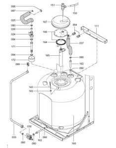
| 111 | | Cylinder mounting bracket | | |
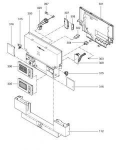
| 112 | | Control unit support | | |
| 130 | | Circulation pump | | |
| 131 | | Circulation pump | | |
| 133 | | Circulation pump motor | | |
| 134 | | Circulation pump motor | | |
| 140 | | Flue gas temperature sensor | | |
| 141 | | Thermocouple | | |
| 142 | | Temperature sensor | | |
| 143 | | Cylinder temperature sensor | | |
| 150 | | T&P valve connection pipe | | |
| 151 | | T&P valve | | |
| 160 | | Cylinder | | |
| 162 | | Sleeve | | |
| 163 | | Strain relief | | |
| 164 | | Cylinder gasket | | |
| 166 | | Anode flange with gasket | | |
| 167 | | Flange insulation | | |
| 171 | | Sleeve | | |
| 172 | | Lid | | |
| 200 | | Side panel, left | | |
| 202 | | Side panel, right | | |
| 204 | | Top cover | | |
| 205 | | Front panel, top | | |
| 206 | | Bottom front panel | | |
| 207 | | Adjustable foot | | |
| 208 | | Fixing elements | | |
| 300 | | Control unit | | |
| 301 | | Casing back panel | | |
| 302 | | Boiler coding card | | |
| 303 | | Fuse 6.3 A slow (10 pce.) | | |
| 304 | | Fuse holder | | |
| 305 | | Programming unit for weather compensated mode | | |
| 306 | | Programming unit for constant temperature mode | | |
| 307 | | LON communication module (accessories) | | |
| 308 | | PCB adaptor, LON module (accessories) | | |
| 309 | | Internal extension H1 | | |
| 315 | | Locking bolts, left and right | | |
| 316 | | Slider, left and right | | |
| 60 | | Burner gasket | | |
| 61 | | Insulation ring | | |
| 64 | | Ignition electrode with gasket | | |
| 65 | | Ionisation electrode with gasket | | |
| 165 | | Magnesium anode | | |
| 108 | | Special grease | | |
| 209 | | Touch-up paint stick, Vitowhite | | |
| 210 | | Spray paint, Vitowhite | | |
| 310 | | Cable harness X8/X9/Ionisation | | |
| 311 | | Cable harness 100/35/54 (auxiliary earth) | | |
| 312 | | Cable harness stepper motor | | |
| 313 | | Mating plug | | |
| 314 | | Cable fixing | | |
| 400 | | Operating instructions for constant temperature mode | | |
| 401 | | Operating instructions for weather compensated mode | | |
| 402 | | Installation and service instructions | | |